Select
a default 192 kHz config using
the "new session" icon (the far left button of the six above the big
blue window). Use the "192 kHz minimum" choice. Delete all the input
strips using the
little "X" in the upper left hand corner. You will be asked if you're
sure about each step, but go ahead and delete them until there are no
strips left. Add a new strip using the "*" in the upper left hand
corner. You will get the dialog window below.
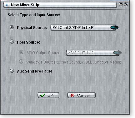
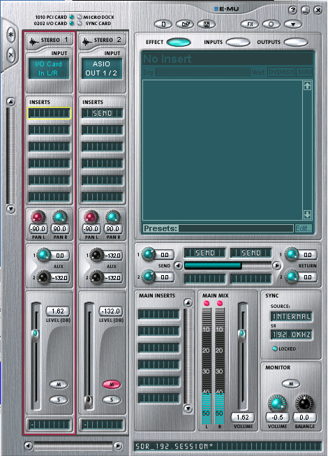
Select Physical Source, then click on the blue oval and select "I/O Card IN L/R". Pan L should be panned to -90 and Pan R to +90. This routes the sound card line input to BUS 1.
Select Physical Source, then click on the blue oval and select "I/O Card IN L/R". Pan L should be panned to -90 and Pan R to +90. This routes the sound card line input to BUS 1.
Add another new strip and choose Host Source. Click on the blue oval and select ASIO OUT 1/2. Once again, the pans should be set for +/-90.
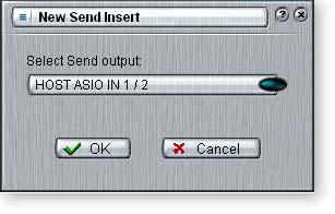
Insert a Send by right clicking in the top insert field, and select OUT 1/2 I/O Card. This inputs the sound from PowerSDR and routes it to the sound card output jack. Click the little M to mute the strip... this removes the strip's output from BUS 1 so that it doesn't mix with the sound card input.
In the BUS 1 output section, just below the big window, right click in the left most insert field and select ASIO IN 1/2. This sends the bus output to PowerSDR's ASIO input.
In the insert field to the right of that one, right click and select Wave L/R Host. This routes BUS 1 to CW Skimmer (using MME or WDM input).
Your setup should look like mine when you're done. Save the session. I have posted my session file in the Files section of the LP-PAN Yahoo Group website.
Below is a picture of what the PowerSDR Audio Setup tab should look like for this card. You may or may not need the Expert mode selected. On my older PC, setting a latency of 2ms helped the card start reliably. All other settings should be matched exactly as shown, except "Line In Gain", "Mic In Gain" and "Output Voltage" which are meaningless in the context of LP-PAN.

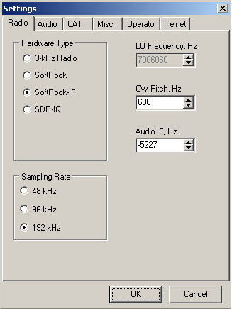
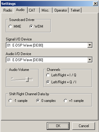
If you plan to use CW Skimmer
simultaneously with PowerSDR, use the following pictures as a guideline
for setting up Skimmer. Your
"Audio IF, Hz" setting will be different than mine. A ballpark setting can be found using this formula...
CW Pitch - Global Offset = Audio IF, Hz
CW Pitch is the setting in the K3. It should also be set in PowerSDR and LP-Bridge to match.
Global Offset is the setting in PowerSDR>Setup>SoftRock IF Stage tab. You will need to fine tune it after the initial setting. Use the default CW filter in the K3 when doing this. Make sure the DSP controls are set to NORmal, as they shift the Skimmer display if not.