Material on this web site
copyright
© 1995-2011, TelePost, Inc. All rights reserved.
Pricing and specifications subject to change without notice.
LP-Remote
Remote control software and hardware
combination.
LP-Remote is a limited run product. I
keep PCBs and many of the parts on hand, but order things like the LCD
and relays as I get orders. Contact me for pricing information at email. The LP-Remote board is
available as a kit or
assembled. Expect about 2 weeks for delivery.
Ordering:
The LP-Remote board is available in kit or assembled form. Email us for details on
pricing/ordering. The Manual for LP-Remote covers assembly (for the kit
version), setup and operation of both the hardware and software. You
can access it in html format here,
or in pdf format here. To download
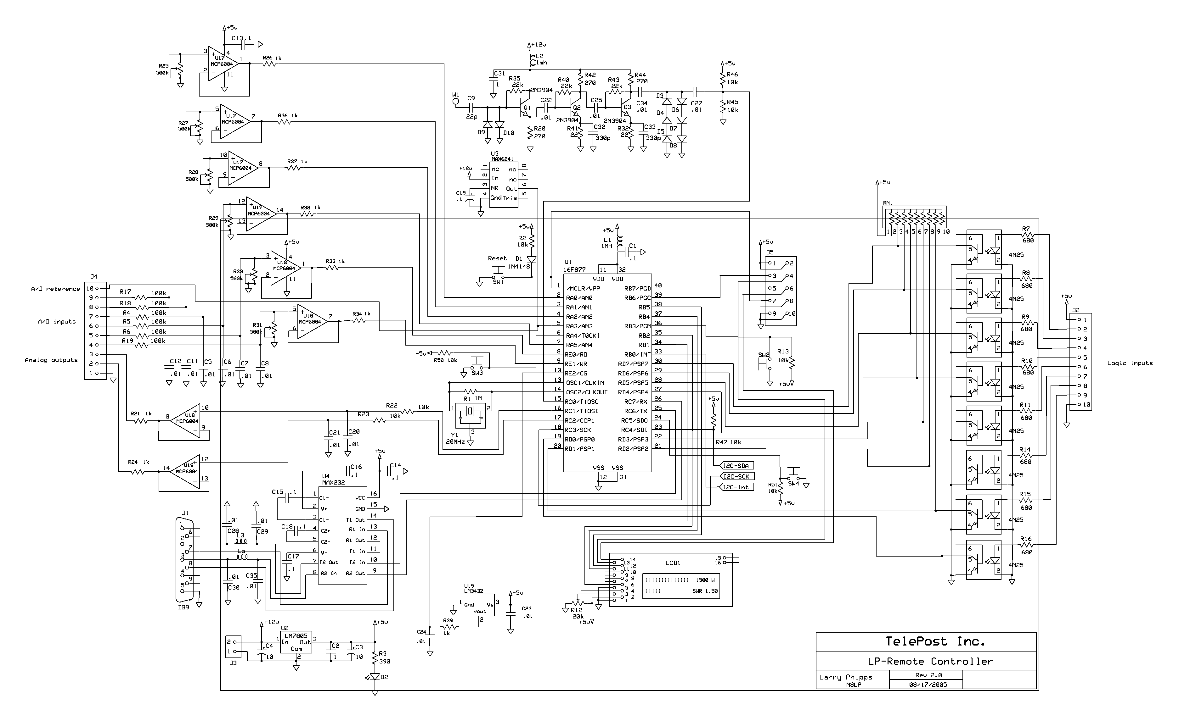
hi-resolution schematic pages, right click here
and here,
save to disk and
then open with MS Paint and print.
Software---
The current version of LP-Remote firmware is version 1.04, and
LP-Remote software is 1.05.
Back
to Home
We are beta testing a new application which allows programming of
relays through macros which provide the capability of sequencing groups
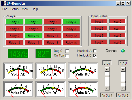
of relays with a single button press. The version shows the status of
up to 64 relays, and allows the relays to be individually toggled by
pressing the status buttons in addition to using a macro button
to control them. Below is a picture of the new program showing 32
relays.
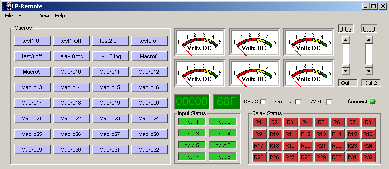
Both software panels allow for full customization of meters, buttons
etc. The windows can be collapsed to eliminate the meters and
sliders if desired, or expanded to show serial comm data for
troubleshooting. The relay buttons light to show the actual remote
relay driver
status...
We don't assume commands were received at the remote site! A/D update
rates
are adjustable from 100 milliseconds to 2 sec. All 6 meters are sampled
at the same
time,
as well as the digital status inputs. There is a flashing "Connect"
indicator
to verify the remote connection and speed. The software displays
transmitted frequency, and the frequency counter can also be used as a
reset input for the watchdog timer. Board temperature is also displayed
in degrees F or C.
The program will work with desktop remote control programs
like
pcAnywhere, winVNC and XP Remote Desktop of course. And, as always,
will
be able to be used with serial device servers as documented in the Remote
Control of Networked Station Equipment section of my website.
Below is an example of the setup
page. In addition, we plan to offer automatic relay selection based on
frequency (using the board's frequency counter) and the option to pulse
the relays. We hope to release a fully functional version of
the program in the near future.

With this design, the relays can be controlled in any combination to
handle a variety of tasks, including antenna tuning, direction
switching
for antennas like the 4-square or beverage, routing of transverters,
etc.
In this example linear amplifier bandswitching is handled by band data
hardwired
from the rig, but relays could be used as well.
The Manual for LP-Remote covers assembly (for the kit
version), setup and operation of both the hardware and software. You
can access it in html format here,
or in pdf format here. To download
hi-resolution schematic pages, right click here and here, save to disk and
then open with MS Paint and print.
Downloads---
The standard version can be downloaded here...
http://www.telepostinc.com/Files/LP-Remote_v105.zip
The beta software can be downloaded here...
http://www.telepostinc.com/Files/LP-Remote_beta.zip
A basic help file on how to use the beta is located here.
To use the beta, first install the standard full version and make sure
it works. Then download and unzip the beta. You will have a new
LP-remote.exe file after unzipping. Rename the LP-Remote.exe file
currently in your LP-Remote folder to something like LP-Remote.old, and
then place the new LP-remote.exe in the same directory.
Here's how the beta works...
On the Setup page, select the Macro A tab. Enter a name for the first
macro (or leave the name as Macro1). Enter a string of relay numbers to
turn on, and/or a string to turn off. The relay codes must be two
digits, and are one number less than the relay number, ie. Relay 1=00.
Use a comma between relays, and a semi-colon at the end. Don't use
spaces.
For instance, to turn on relays 1 thru 3, type 00,01,02; in the
On box To turn off the same relays, type in the Off box instead.
If you type in both On and Off boxes, you can turn on some relays and
at the same time turn off others, for instance...
On box = 00,01,02; and Off box = 06,07; would turn on relays 1-3 and
turn off relays 7&8.
If you enter the same relays in both boxes, it will cause those relays
to toggle each time you click the button for that macro, BUT be careful
that you don't use those relays for anything else, or they could get
out of sequence. It's safer to not use the same relays in both boxes,
but you should be able to use the toggle function with a little care.
You can click on the status buttons for the relays instead of a macro
button if you want to toggle that relay only, but you'll have to
remember what the relay controls. The status buttons work like the old
relay buttons, but don't have names... just numbers. You should program
macros for all the functions you used to use.
One warning for existing users...
this software only works with firmware v1.0.4.
Some of the defaults may not appear until you use the new functions so
that
their state can be saved in the Registry.
Hardware---
Here is a picture of the production board mounted on an aluminum panel.
It is silk-screened and solder masked for
easier assembly of the kit version.
The relay outputs are on the top and bottom right of the board, the
expansion port is on the right edge, the digital inputs and analog
inputs/outputs are on the top left, the +12v power, frequency counter
input
and serial port are on the left edge.
The board provides screw terminals for all I/O connections,
allowing easy custom installation to meet the users needs. All critical
parts are socketed. I tried to isolate the board
from the shack as much as possible, using dry relay contacts, opamps
and
opto-isolators. The analog ports are all opamp buffered as well to
protect the PIC from dangerous signal levels, and provide hi-Z inputs.
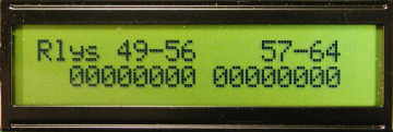
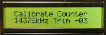
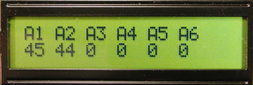
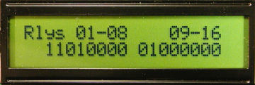
The large LCD screen, in addition to the Home screen shown above,
is used for setting up and monitoring the board. The six screens below
show analog inputs, digital inputs, analog outputs, relay status for
relays 1-16 and 49-64... and frequency counter calibration screen.


The board is expandable as far as
relays are
concerned. It provides the following connections...
6 10-bit buffered analog inputs with precision 2.5v reference
and adjustable gain
2 buffered variable analog outputs (0-5 vdc)
8 digital status inputs with opto-isolators
16 10A SPDT relays, expandable to 64 in groups of 16 with additional
relay expansion boards (expansion boards are special order).
LCD status display to aid in setup and maintenance
Menu selector switches for display
Built-in 30 mHz frequency counter with either 50 ohm, -30 dBm to +20
dBm input range or 10mW to 150W hi-z bridging.
Built-in precision thermometer
Gnd
A/D reference output
+12 vdc
Serial port for control
Relay expansion port
Watchdog Timer with multiple reset sources
Remotely controllable through serial servers
The Manual for LP-Remote covers assembly (for the kit
version), setup and operation of both the hardware and software. You
can access it in html format here,
or in pdf format here.
Customization:
Below is a picture of one of the first boards installed at
KP2A. I
provided John with an LP-Remote board with a Lantronix UDS200 serial
server, interfacing for AC line voltage, charge state of the deep cycle
battery that powers the station and a Top Ten devices antenna switch.
The Lantronix also provides rig control.
I will provide details of the protocol for communicating with the
LP-Remote board so that you can write your own software if you like.
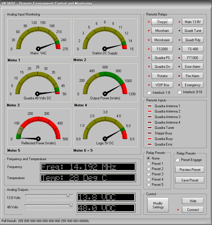
Here is a screen grab of the software written by VK3ADE for his
LP-Remote board. This is one of the nicest looking pieces of control
software I have seen. Great job, Roger!
Back
to Top